
(1) Definition and Functions
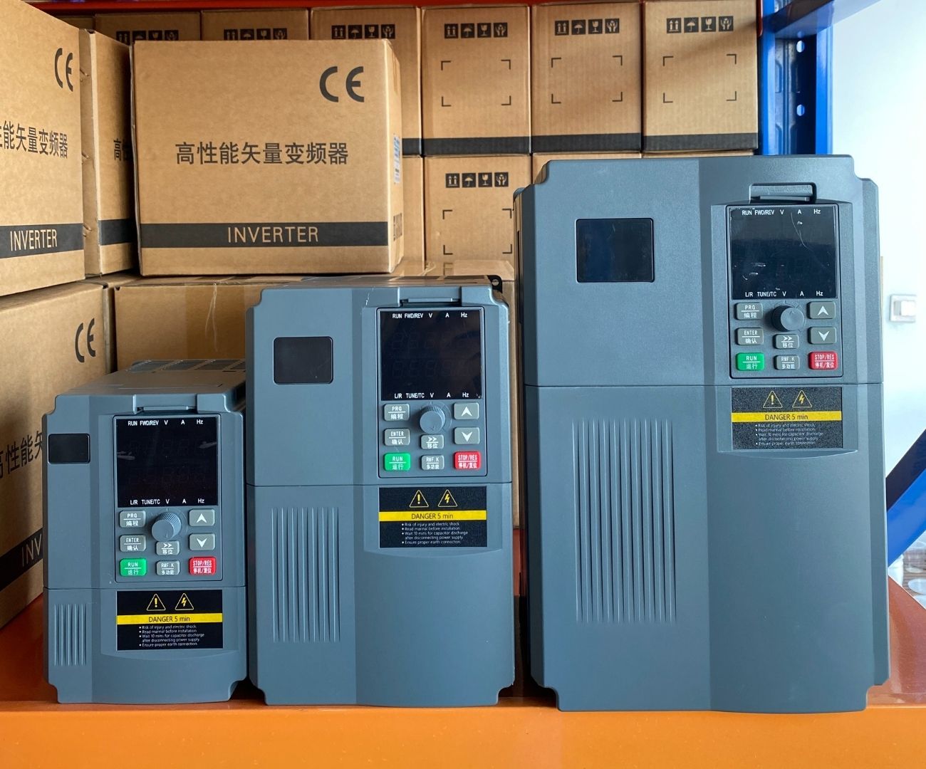
An inverter, fully known as a Variable-frequency Drive (VFD), is an electrical control device that applies frequency conversion and microelectronics technology to control AC motors by altering the frequency of the motor’s power supply. Essentially, it acts as a “pace controller” for the motor, accurately transforming fixed-frequency AC power into continuously adjustable frequency and voltage AC power, providing a customized power supply for the motor.
Speed regulation is the core function of an inverter. Based on the close relationship between motor speed and power supply frequency (n = 60f/p, where n is the motor speed, f is the power supply frequency, and p is the number of motor pole pairs), an inverter can easily achieve precise speed adjustment of the motor by changing the power supply frequency. In industrial production, the operating speed of many devices needs to be flexibly adjusted according to different process requirements. In the textile industry, factors such as yarn thickness and fabric type require precise control of the speed of textile machinery. The application of inverters enables textile machinery to operate stably under different working conditions, producing high-quality textiles.
Energy saving is another major highlight of inverters. In equipment such as fans and pumps, the load power is proportional to the cube of the speed (P∝n³). When the actual demand decreases, reducing the motor speed through the inverter can significantly lower energy consumption. According to relevant data, in central air conditioning systems, using inverters to control the speed of chilled water pumps and cooling water pumps can achieve an average energy saving rate of over 30%. This not only saves enterprises a significant amount of electricity costs but also aligns with the current trend of energy conservation and emission reduction in society.
(2) Basic Structure
An inverter mainly consists of four parts: the rectifier unit, the DC intermediate link, the inverter unit, and the control unit. Each part has a unique and critical mission, and they work closely together to ensure the efficient and stable operation of the inverter.
Rectifier Unit: Like a diligent “current translator,” the main task of the rectifier unit is to accurately convert the input industrial frequency AC power (usually 380V, 50Hz) into DC power. It is generally composed of diodes or thyristor rectifier bridges. Through clever circuit design, it integrates the alternating positive and negative waveforms of AC power into smooth DC waveforms, providing a stable DC power supply for subsequent circuit stages.
DC Intermediate Link: This is a “energy storage station” that plays a key role in buffering and storing energy. It mainly consists of filter capacitors and reactors. The filter capacitors effectively smooth the DC voltage, eliminating voltage fluctuations and spikes, ensuring the stability of the DC voltage. The reactors, on the other hand, suppress sudden changes in current, improve the power factor, and reduce harmonic pollution to the grid, like a meticulous housekeeper maintaining the stable order of the circuit. Inverter Unit: As the core “magician” of the inverter, the inverter unit’s responsibility is to magically convert the DC power output from the DC intermediate link into AC power with adjustable frequency and voltage to meet the speed regulation needs of different motors. It is usually composed of multiple high-speed switching devices (such as IGBTs). Under the command of the control unit, these switching devices alternately turn on and off at extremely high speeds. By precisely controlling the timing and sequence of the switching, they cleverly synthesize the required frequency and voltage AC waveforms, providing precise power drive for the motor.
Control Unit: The control unit can be called the “intelligent brain” of the inverter. It is responsible for receiving various operation commands (such as start, stop, accelerate, decelerate, etc.) and sensor feedback signals. Then, based on preset algorithms and programs, it quickly and accurately processes and analyzes these signals, finally issuing precise control signals to command the rectifier unit, DC intermediate link, and inverter unit to work together, achieving precise speed regulation of the motor and various protection functions, ensuring the safe and stable operation of the entire system.
(3) Detailed Working Principle
Currently, commonly used inverters mostly adopt the “AC-DC-AC” conversion method. Its working process is like a spectacular electrical “magic show,” with each step full of scientific charm and engineering wisdom.
Rectification Stage: In this initial stage, the input industrial frequency AC power first enters the rectifier unit. The diodes or thyristor rectifier bridges in the rectifier unit, like a group of well-trained “current guides,” follow specific rules to orderly guide and integrate the positive and negative half-cycles of the AC power, converting it into unidirectional DC power. Taking a three-phase bridge rectifier circuit as an example, it can perfectly convert three-phase AC power into smooth DC voltage through the coordinated work of six diodes, providing a stable DC power foundation for the subsequent inversion stage.
DC Intermediate Link: Although the direction of the rectified DC power is fixed, there are still some fluctuations and ripples in the voltage. At this point, the filter capacitors and reactors in the DC intermediate link play an important role. The filter capacitor, like a huge “power sponge,” can absorb voltage fluctuations, making the DC voltage smoother and more stable. The reactor, like a sturdy “current dam,” can suppress sudden changes in current, improve the power factor, reduce harmonic interference to the grid, and ensure the purity and stability of the DC power supply.
Inversion Stage: The inversion stage is the core part of the inverter’s working principle and the climax of this electrical “magic show.” In the inverter unit, the inverter circuit composed of high-speed switching devices such as IGBTs, under the precise control of the control unit, performs high-speed turn-on and turn-off operations according to specific rules and sequences. This process is like a precise dance, with every action of the switching devices carefully designed. By cleverly controlling the timing and sequence of the switching, the DC voltage is cut into a series of pulse voltages with different widths and intervals. These pulse voltages, after the inductive filtering effect of the motor windings, can synthesize an approximate sine wave AC power, thereby achieving precise control of the motor speed and torque.
In the inversion process, Pulse Width Modulation (PWM) technology and Space Vector Modulation (SVM) technology are key to achieving efficient and precise control. PWM technology adjusts the average value of the output voltage by changing the width of the pulses, making it equivalent to the required sine wave voltage. Simply put, by controlling the turn-on time of the switching devices, the width of the output rectangular wave pulses is adjusted according to the amplitude variation law of the sine wave, thereby generating an approximate sine wave current in the motor windings, achieving smooth speed regulation of the motor. SVM technology, on the other hand, approaches from the perspective of space vectors, by reasonably selecting and combining the switching states of the inverter, making the output voltage vector of the inverter form a circular rotating magnetic field in space, thereby achieving high-performance control of the motor. SVM technology not only improves the utilization of DC voltage and reduces harmonic components but also effectively reduces the torque ripple of the motor, improving the operating efficiency and stability of the system.
Leave Comment